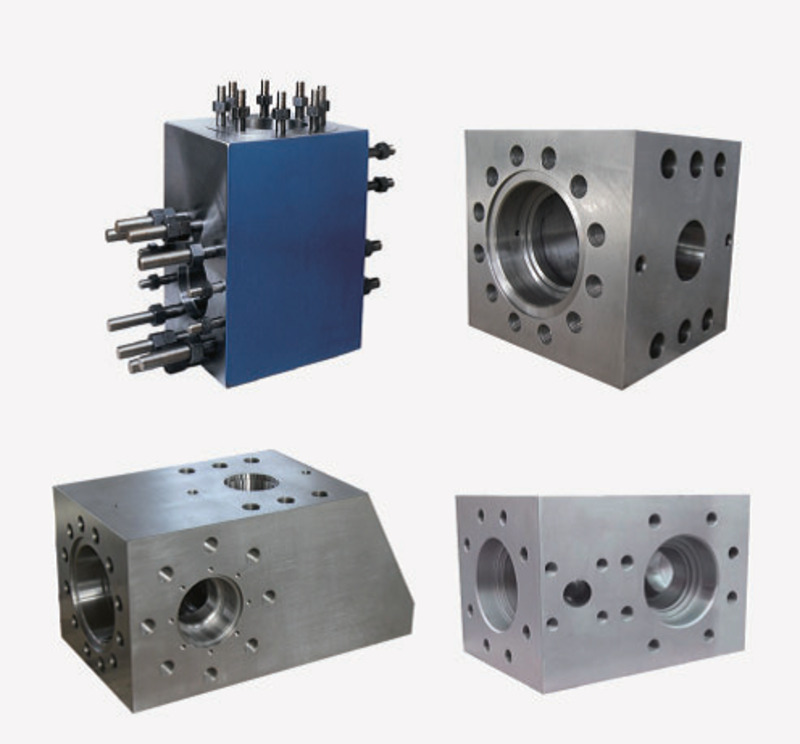

A mud pump valve seat is a precision sealing surface, not a generic ring of hardened steel. Together with the valve body, insert, spring and fluid-end bore, it controls one-way drilling-fluid flow during every pump stroke. A seat that is incorrectly specified, poorly installed or reused beyond its serviceable condition can contribute to leakage, pressure fluctuation, wash damage and avoidable downtime.
This field guide gives drilling contractors, maintenance teams and procurement specialists a practical framework for selecting, inspecting and diagnosing mud pump valve seats. It emphasizes verifiable application data and observable failure evidence rather than unsupported service-life claims.
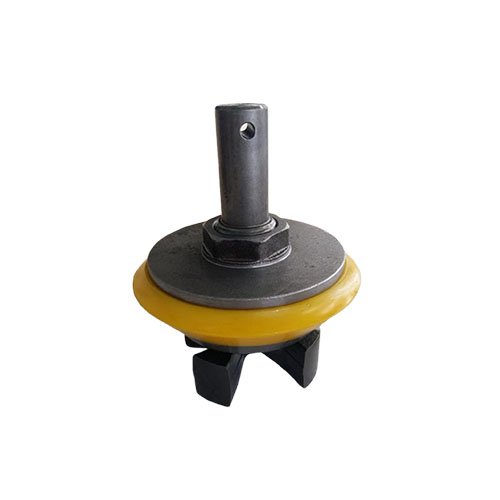
How a Mud Pump Valve Seat Works
Triplex and other reciprocating mud pumps use suction and discharge valves to direct fluid through the fluid end. Differential pressure lifts the valve from its seat during the open portion of the cycle. The spring and changing pressure then return the valve to the seat. The contact area must close consistently while the components encounter repeated impact, suspended solids, chemical exposure and high-pressure fluid.
The pumped medium is not uniform across drilling programs. The SLB drilling-mud definition describes water-based, nonaqueous and gaseous fluid categories, including mixtures containing solids. Those differences matter because fluid chemistry, density, solids content and temperature influence sealing inserts, abrasive loading and deposits.
Information to Confirm Before Ordering
1. Pump model, valve size and fluid-end configuration
Record the pump manufacturer, exact model, valve size or series, fluid-end arrangement and the current valve-and-seat part numbers. A general statement such as “fits a 1,600-hp pump” is not sufficient. Similar pump families may use different valve systems, and replacement fluid ends may not match the original build.
Use the equipment manual, a controlled supplier drawing and dimensional checks to verify the application. The site’s Mud Pump Valve and Seat product page provides one inquiry reference, while this alternative mud pump valve and seat configuration shows why a model name alone should not be used as the complete specification.
2. Valve-seat interface
Treat the valve and seat as a matched operating pair. Confirm the valve profile, guide arrangement, insert type, spring, seat geometry and any manufacturer restrictions on mixing components. Even where two parts appear dimensionally similar, contact geometry and material combinations can differ. Ask the supplier to identify the exact interchange basis rather than accepting a visual comparison.
3. Drilling-fluid and operating data
Provide normal and maximum discharge pressure, strokes per minute, fluid density, fluid base, temperature, solids-control condition and the observed failure mode. Avoid specifying “standard mud service” without the job data. The same nominal pump can see very different abrasion, impact and chemical conditions across hole sections and drilling programs.
4. Material and heat-treatment documentation
Valve seats are commonly made from alloy steel with controlled heat treatment, but material grade and hardness should never be inferred from color or appearance. Request a documented material designation, manufacturing revision, dimensional inspection and traceability appropriate to the order. If a supplier states compliance with a standard, ask for the exact product scope and evidence.
API’s published overview identifies API Specification 7K as addressing drilling and well-servicing equipment and including piston mud-pump components. Buyers should confirm which requirements actually apply to the ordered product and verify any licensing claim rather than treating “API” as a blanket approval.
5. Storage and handling condition
Inspect new seats for corrosion, impact marks, burrs and contamination before installation. Protect precision surfaces from contact with loose steel parts during transport. Store elastomeric valve components under the supplier’s stated conditions and rotate inventory according to documented shelf-life guidance.
Installation Practices That Protect the Fluid End
- Isolate and depressurize the pump. Follow the rig’s lockout and safe-maintenance procedure before opening the fluid end.
- Clean the bore and working area. Remove loose solids without damaging the seating surfaces.
- Inspect the fluid-end bore. Look for washing, scoring, corrosion, deformation or previous removal damage.
- Verify the replacement components. Compare markings, dimensions and the controlled part reference before assembly.
- Use approved tools and methods. Install or remove the seat only with procedures suitable for the actual pump and fluid end.
- Install the matched valve components. Check the valve body, insert, spring and guides rather than replacing only the visibly failed piece.
- Confirm free movement and correct assembly. Do not force components or improvise fit.
- Restart under observation. Watch discharge pressure, pulsation, leakage, noise and temperature before returning to full duty.
Never attempt to correct a damaged bore by repeatedly driving in a new seat. That can hide the underlying condition and increase the difficulty of the next removal. Escalate abnormal bore damage for an engineering or manufacturer review.
Why Valve and Seat History Should Stay Together
During routine inspection, record which valve operated on which seat. NOV’s official Mission triplex mud-pump maintenance booklet advises removing sand or mud lodged between the disc and valve body and returning an inspected valve to the same seat from which it was removed. Follow the manual for the pump in service, but the broader maintenance lesson is valuable: mixing wear patterns can complicate diagnosis and sealing performance.
Marking locations during teardown and photographing the components before cleaning creates a useful failure record. It also prevents an apparently serviceable valve from being installed on a different seat without evaluation.
Valve Seat Inspection Checklist
- Sealing band: inspect for continuous contact, localized erosion, pitting, embedded solids and impact marks.
- Outer diameter and retention surfaces: inspect for fretting, galling, wash tracks or removal damage.
- Valve insert: look for cuts, swelling, extrusion, hardening, missing material and uneven compression.
- Valve body and guides: check for wear that could allow poor alignment at closure.
- Spring: compare condition and free length using the manufacturer’s acceptance criteria.
- Fluid-end bore: inspect for damage that could prevent correct seating or retention.
- Debris evidence: record the size and type of solids trapped at the sealing interface.
Measurements should be compared with the pump manufacturer’s limits. A component that “looks acceptable” may still be outside a dimensional or wear limit, while a cosmetic mark may not affect serviceability. Use controlled criteria rather than appearance alone.
Common Failure Patterns and What to Investigate
Cut or washed sealing path
A localized channel can develop when the valve does not seal fully and high-velocity fluid continues through a small gap. Investigate trapped solids, insert damage, misalignment, a damaged seat or bore, and delayed response to an early leak indication.
Uneven contact around the circumference
One-sided or segmented contact may justify checking guide wear, valve alignment, seat installation, bore condition and component matching. Replacing the insert alone may not solve a geometry problem.
Seat looseness or outer-diameter damage
Stop and assess the fluid-end bore and installation method. Repeatedly fitting another seat without correcting the retention problem can lead to more expensive fluid-end damage.
Rapid insert deterioration
Check fluid chemistry, temperature, stored-component age, material identity and whether the insert was damaged during installation. Similar-looking elastomers are not automatically interchangeable.
Procurement Questions That Improve Traceability
- Which pump models, valve sizes and controlled part numbers does this assembly fit?
- Is interchangeability supported by a drawing, dimensional table or manufacturer reference?
- What are the seat and valve-body material specifications and heat-treatment controls?
- What insert compound is supplied, and what are its documented operating limits?
- Which dimensions and inspections appear on the quality record?
- How are batches or lots identified?
- What installation, storage and shelf-life instructions are supplied?
- Can the supplier review photographs and operating data from a premature failure?
For additional product comparison, review the site’s mud pump valve and seat reference and the broader mud pump piston selection guide. These components operate in the same fluid end, so maintenance findings should be evaluated together.
Frequently Asked Questions
Can a new valve be installed on a used seat?
Only if the equipment manufacturer’s procedure and inspection limits allow it. The sealing surfaces and wear pattern must be evaluated. A new valve does not correct a washed, pitted or out-of-tolerance seat.
Should suction and discharge valve seats use the same parts?
Do not assume so. Confirm the actual pump manual, fluid-end layout and controlled part numbers. Some configurations share components; others have application-specific requirements.
What causes mud pump valve leakage?
Possible contributors include trapped solids, damaged inserts, washed sealing surfaces, guide wear, weak or incorrect springs, mismatched components, poor installation and fluid-end bore damage. Diagnosis should use inspection evidence and operating records.
What should an RFQ include?
Include pump make and model, fluid-end configuration, valve size, current part numbers, photographs, operating pressure, strokes per minute, fluid type and density, temperature, failure history, quantity, delivery requirement and requested quality documentation.
Final Takeaway
Reliable mud pump valve seat performance depends on a matched valve system, a sound fluid-end bore, verified material and dimensions, disciplined installation and evidence-based failure review. The most useful purchasing decision is not simply the lowest unit price; it is the option that can be traced to the correct application and supported when field evidence shows abnormal wear.