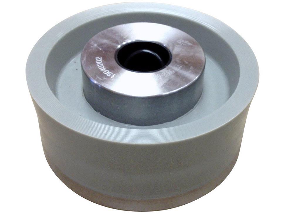

Fluid end modules contain the working interfaces that direct drilling fluid through a reciprocating mud pump. When leakage, wash marks, damaged threads, or abnormal loading appear, the visible symptom may come from the module body, an expendable part, a sealing surface, connecting hardware, or several items acting together. A fast parts swap without preserving evidence can hide the real failure path.
This guide explains how maintenance teams, drilling engineers, and buyers can inspect Fluid End Modules as pressure-boundary assemblies and prepare a controlled changeout. It focuses on external evidence, machined interfaces, hardware, documentation, and procurement data. It does not provide universal rejection limits, pressure ratings, torque values, or service-life claims; those must come from the correct manufacturer documentation and the site’s approved procedures.
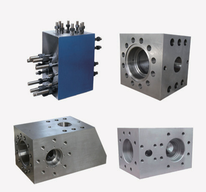
Why inspect the module as a pressure-boundary system?
A module is not just a block that holds wear parts. Its valve pockets, liner connections, covers, retainers, manifolds, studs, and sealing shoulders must remain correctly aligned and loaded. A wet track near one interface can originate at a gasket or expendable, while repeated leakage at the same location may justify a closer review of the receiving surface, thread, pocket, or adjacent hardware.
Start with the site’s Fluid End Module product page to identify the relevant product family. Then separate the module body from the parts listed on the Fluid End Expendables page. This distinction matters because replacing a valve, seat, gasket, liner, or retainer will not correct unacceptable damage in the module interface that supports it.
Preserve evidence before cleaning or disassembly
Record the operating symptom while it is still observable. Note when it started, its location, whether it changes with pump speed or pressure, and any work performed shortly beforehand. Photograph the complete fluid end from consistent angles, then capture close views with a scale reference. Mark the module position and orientation so the removed parts can be traced back to the correct pocket or cylinder.
Look for wet paths, dried residue, rust trails, localized polishing, fretting debris, damaged coatings, or loosened hardware. These observations are not a diagnosis by themselves, but they help direct the inspection. Before opening the fluid end, isolate pressure and energy according to the rig’s approved procedure and confirm that the system is safe to work on.
A staged inspection for Fluid End Modules
1. External body and transition areas
After documenting the as-found condition, clean the module using an approved method that will not damage surfaces or erase needed evidence. Inspect accessible faces, port transitions, pocket edges, and geometry changes under suitable lighting. Suspected indications should be recorded by location and orientation. A photograph cannot confirm whether a line is a crack, machining mark, stain, or surface damage, so do not assign a failure mechanism without appropriate examination.
If nondestructive examination is required, the method, surface preparation, acceptance criteria, and personnel qualification should follow the applicable manufacturer, engineering, and site requirements. Avoid inventing a reject rule from an unrelated module design.
2. Valve pockets, liner connections, and sealing shoulders
Inspect the surfaces that locate valves, seats, liners, covers, and retainers. Look for dents, raised metal, erosion, galling, damaged threads, embedded solids, corrosion, or an incomplete contact pattern. Compare similar positions in the same assembly, but remember that equal appearance does not prove dimensional compliance.
Check the mating parts at the same time. A damaged cover, gasket, seat taper, liner flange, or retainer can create evidence on the module surface. Keep removed parts labeled by position until the cause review is complete. The recent Fluid End Modules procurement and inspection guide covers general incoming checks; this article concentrates on installed pressure-boundary evidence and changeout readiness.
3. Studs, nuts, threads, and contact faces
Review studs and nuts for traceable identity, visible deformation, corrosion, damaged threads, and signs of uneven loading. Inspect module-to-frame, module-to-module, manifold, and jewelry contact surfaces where accessible. Dents, high points, contamination, or uneven seating can prevent consistent load transfer.
The official NOV Mission application and troubleshooting guide states that module contact surfaces should be flat and free from dents, high points, and contaminants. It also describes clean anti-seize, an alternating crisscross tightening pattern, and manufacturer-recommended torque for relevant Mission equipment. Apply those instructions only where the specific configuration and OEM documentation support them.
Distinguish a module problem from an expendable problem
- Leakage at a cover or retainer: inspect the seal and hardware, but also examine the module thread, shoulder, and contact face.
- Repeated valve-seat movement or wash: preserve the seat and valve evidence and inspect the receiving pocket or taper before installing another set.
- Liner-area leakage: check the liner, gasket, retainer, alignment, and module connection rather than blaming one visible component immediately.
- Uneven stud or nut condition: review contact-face seating, tightening records, hardware identity, and any alignment issue.
- External line or indication: stop assigning a cause from appearance alone and route it through the approved engineering or NDE process.
Trend recurrence by position. If the same pocket or interface repeatedly shows the same symptom while neighboring positions do not, that pattern is useful evidence. It still needs measurements, component history, and the correct acceptance criteria.
Build a changeout-readiness package before downtime
A replacement module can be physically present yet not ready to install. Before the shutdown window, confirm the pump manufacturer and model, module configuration, cylinder position, relevant part numbers, drawing revision, connection arrangement, valve and liner sizes, manifold interface, stud package, covers, retainers, gaskets, lifting points, and required tools. Verify each item against controlled documentation rather than against appearance alone.
Prepare protective caps and clean storage for exposed openings. Review the lifting plan, work area, support equipment, alignment steps, fastener procedure, and inspection hold points. Confirm who is authorized to approve an unexpected pocket, thread, or contact-face condition. A clear stop-work decision path prevents rushed acceptance during reassembly.
NOV’s official Fluid End Modules resource illustrates that module designs, features, ratings, and pump applications vary across product families. It should not be used to infer compatibility for a different module. Match the proposed replacement to the actual pump and controlled technical data.
What buyers should include in a Fluid End Modules inquiry
Send the pump make and model, existing module part number, serial or traceability markings, module configuration, valve and liner sizes, known pressure and fluid service, connection details, and clear photographs of every side. Include drawings or dimensional reports with revision numbers where available. Describe whether the request is for a bare block, studded module, assembled package, or a module with selected jewelry and expendables.
The API Specification 7K overview describes general design, manufacture, and testing scope for piston mud-pump components. Referencing that scope does not prove that a particular module is certified, API Monogrammed, interchangeable, or acceptable for a specific service. Verify the manufacturer’s license scope and the product documentation independently.
For help organizing a request, use the site’s service contact page. A concise data package reduces quotation ambiguity and gives engineering and procurement teams a common basis for review.
Pre-changeout checklist
- Confirm energy isolation, drainage, access, lifting, and approved work instructions.
- Photograph and label module positions, interfaces, hardware, and removed parts.
- Verify replacement identity, drawing revision, configuration, and required accessories.
- Inspect the new or refurbished module’s protected openings, threads, contact faces, and shipment condition.
- Prepare traceable studs, nuts, seals, retainers, covers, expendables, tools, and calibrated equipment where required.
- Define inspection hold points and the person responsible for accepting unexpected conditions.
- Plan post-assembly checks and the approved start-up monitoring sequence.
Frequently asked questions
Can an external stain prove that a fluid end module is cracked?
No. A stain or line is an indication to investigate. Cleaning, examination, measurements, and the approved engineering or NDE process are needed before classification.
Should a module be replaced whenever an expendable leaks?
No. The failed expendable, its mating interface, hardware, installation history, and the module condition should be evaluated together.
Can module compatibility be confirmed from photographs?
Photographs help, but they are not sufficient. Part numbers, pump model, drawings, dimensions, configuration, and controlled manufacturer data are also required.
What torque value should be used on module hardware?
Use the value and sequence specified for the exact pump, module, hardware, and procedure. A generic article should not supply a universal torque.
Does an API 7K reference prove API Monogram status?
No. A standard reference identifies scope or requirements. Product certification and the manufacturer’s licensed scope must be verified separately.
Summary
Reliable Fluid End Modules changeouts begin with evidence, not assumptions. Document the operating symptom, inspect module and expendable interfaces together, evaluate contact faces and hardware with the correct criteria, and assemble a traceable replacement package before downtime. This approach supports safer maintenance decisions, clearer supplier communication, and a more controlled return to service.