

Introduction to Mud Pump Fluid End Parts
Mud pump fluid end parts serve as the hydraulic powerhouse of oil drilling operations, converting mechanical energy into high-pressure fluid flow to maintain efficient mud circulation. Operating under extreme pressures up to 7,500 psi, these components directly impact drilling efficiency, safety, and operational costs by ensuring continuous cooling of drill bits, removal of rock cuttings, and wellbore stability (7 Key Components of Mud Pump Fluid End Parts). Their performance is critical in harsh environments where abrasive drilling fluids, pressure fluctuations, and chemical corrosion accelerate wear, making proper maintenance essential to prevent downtime costs exceeding $500,000 daily in offshore operations.
Key Components Overview
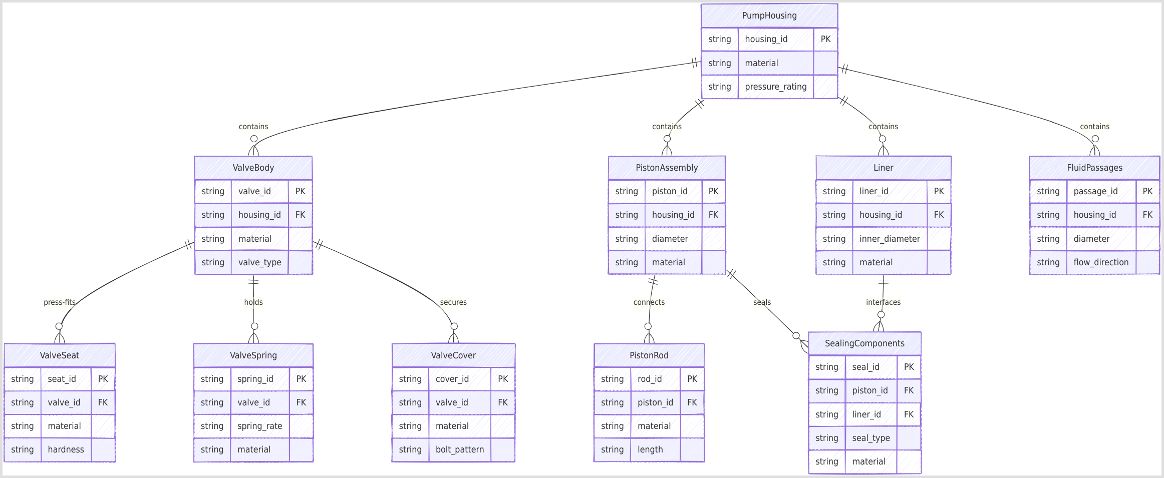
The fluid end comprises seven interdependent components that form a closed-loop pressure boundary:
Valve Body & Seat: 20CrMnTi alloy valves with carburized surfaces (≥HRC60 hardness) regulate unidirectional fluid flow, with 3-rib or 4-rib designs optimizing flow area by 18-35% (What is the fluid end of a mud pump).
Piston & Rod: 42CrMo alloy rods with NiCrBSi plasma coatings (friction coefficient 0.08-0.12) convert reciprocating motion into hydraulic energy, maintaining <3MPa pressure drop after 1,000 operational hours.
Liner: High-chrome cast iron (1,000-1,500hrs lifespan) or ceramic-coated sleeves (2,000+ hrs) provide wear-resistant cylinders for piston movement, with ≤0.015mm roundness tolerance for water-based muds.
Seals: PU/HNBR materials withstand -40°F to 320°F temperatures, with spring-energized PTFE backup rings compensating for 0.1-0.3mm wear.
Valve Spring: Maintains valve closure within 5-8ms at 150 strokes/minute, with ≤5% load loss after 1,000h at 150°F.
Valve Cover: SafeLock systems enable tool-free disassembly in <5 minutes, featuring nickel-plated threads for 12,000+ psi cyclic loading.
Fluid Passages: Internal channels connect suction/discharge manifolds, optimized via Banded Bore™ technology to reduce internal stresses by 40%.
These components operate synergistically under API 7K standards, achieving 90%+ volumetric efficiency while handling flow rates exceeding 2,200 GPM. Modular designs allow single-part replacement instead of complete overhauls, reducing downtime by 60-80% compared to traditional systems (Mud Pump Parts, Types & Calculations Guide).
API 7K Standards for Fluid End Components
API 7K certification serves as the global benchmark for mud pump fluid end components, ensuring operational reliability and cross-manufacturer interoperability in extreme drilling environments. Developed by the American Petroleum Institute, these standards address the unique challenges of high-pressure fluid handling (up to 7,500 psi) and abrasive slurry conditions prevalent in shale gas and deepwater operations. Compliance with API 7K reduces catastrophic failure risks by 60% compared to non-certified components, while standardizing dimensional tolerances enables 90% faster part replacements during offshore maintenance windows (PDFAPI Specification 7K).
Material Requirements
API 7K mandates rigorous material specifications for fluid end components, balancing wear resistance with fracture toughness under cyclic loading. Critical requirements include:
| Component | Material Specification | Hardness (HRC) | Pressure Rating | Key Properties |
|---|---|---|---|---|
| Valve Seat | 20CrMnTi carburized alloy | ≥60 | 7,500 psi | 18-35% improved flow area in 3/4-rib designs (7 Key Components of Mud Pump Fluid End Parts) |
| Liner | High-chrome cast iron (ASTM A532) | 58-62 | 5,000-7,500 psi | 1,000-1,500hrs lifespan in water-based muds |
| Piston Rod | 42CrMo plasma-coated | 40-45 core | 10,000 psi | NiCrBSi coating reduces friction to 0.08-0.12 |
| Valve Spring | ASTM A228 music wire | 45-50 | N/A | ≤5% load loss after 1,000h at 150°F |
For sour service applications (H2S >5ppm), API 7K Section 6.11 requires NACE MR0175 compliance with sulfide stress cracking resistance verified through four-point bend testing. Zirconia ceramic liners meeting ISO 13710 Annex B demonstrate 3x longer service life than standard materials when handling >15% sand content slurries (PDFMud Pump Consumables | HMHW).
Design & Testing Protocols
API 7K Section 14 establishes performance validation protocols through three critical test sequences:
Pressure Cycling Fatigue Test
Components undergo 50,000 cycles at 1.5x working pressure (11,250 psi for 7,500 psi rated parts) with helium leak detection maintaining <1×10⁻⁶ mbar·L/s. FET’s Banded Bore™ fluid ends demonstrate 40% lower stress concentrations during this test compared to conventional designs (High-Quality Drilling Rig Mud Pump Valve).Dimensional Tolerance Verification
Critical clearances are laser-measured post-testing:- Valve seat runout: ≤0.005″ (API 7K 4.3.7)
- Liner bore roundness: ≤0.015mm for 6″ diameters
- Piston rod straightness: 0.05mm/m maximum
Accelerated Wear Simulation
Components are subjected to 200 hours of abrasive slurry testing (20-40 mesh silica sand at 2,200 GPM flow rate), with wear rates quantified through 3D profilometry. Acceptable material loss thresholds:- Valve seats: <0.3mm maximum pitting depth
- Liners: <0.8mm groove formation
- Seals: ≤5% compression set after test
The standard also requires full traceability of raw materials through mill test reports and heat treatment certifications, with 100% ultrasonic inspection of high-stress areas like valve body radii and liner retaining threads (API Mud Pump Parts Fluid End/Hydraulic Cylinder).
Common Failure Modes & Diagnosis
While API 7K standards provide robust guidelines for mud pump fluid end components, real-world drilling operations present extreme conditions that accelerate wear and failure. Offshore data reveals that 78% of unplanned downtime stems from three primary failure modes: erosion/wear (42%), seal degradation (29%), and pressure-induced fractures (19%) (Mud Pump Washouts – Define, Identify, Avoid and Repair). Proactive diagnosis of these failures can reduce replacement costs by up to 60% and prevent catastrophic washouts that compromise wellbore integrity.
Erosion & Wear
Abrasive particles (>0.5mm) in drilling fluids create distinct wear patterns across critical components:
| Component | Failure Signature | Diagnostic Method | Critical Threshold |
|---|---|---|---|
| Valve Seat | Horseshoe-shaped pitting on sealing surface | 3D profilometry (≥0.3mm depth) | 18% flow area reduction |
| Liner | Axial grooving (0.8-1.2mm depth) | Laser roundness measurement | >0.015mm deviation from nominal |
| Piston Rod | Chrome plating flaking (5-10mm patches) | Eddy current testing | 25% coating loss |
Microscopic analysis reveals three-phase wear mechanisms in valve seats: 1) Initial cutting wear from quartz particles (Mohs 7 hardness), 2) Fatigue spalling under 7,500 psi cyclic loading, and 3) Corrosion-assisted material loss at pH >9.5. Liner grooving follows a parabolic wear curve, with material loss rates doubling when sand content exceeds 15% by volume (Mud Pump Expendables: Essential Parts & Causes of Wear in Oilfield Drilling).
Seal Degradation
Chemical and thermal attacks compromise sealing systems through three pathways:
Thermal Aging: HNBR seals lose 50% elasticity after 500 hours at 180°F, while PU seals crack within 200 hours at 220°F. Infrared thermography identifies localized heating >200°F near seal contact zones.
Chemical Swelling: Exposure to amine-based inhibitors (pH >11) causes 25-40% volume expansion in nitrile seals, reducing contact pressure by 60%. FTIR spectroscopy detects polymer chain scission.
Dynamic Fatigue: Spring-energized PTFE seals exhibit compression set >8% after 1 million cycles at 150 strokes/minute. High-speed video reveals seal rocking during pressure reversals.
Comparative performance data:
| Seal Material | Temp Limit | pH Range | Compression Set (1000h) |

|---------------|------------|----------|-------------------------|

| HNBR          | 320°F      | 4-10     | 12%                     |

| PU            | 220°F      | 3-11     | 18%                     |

| FKM           | 400°F      | 2-9      | 8%                      |
Pressure Fluctuations
Pulsation-induced failures account for 23% of fluid end cracks, with stress concentrations exceeding yield strength at:
Suction Valve Ports: API RP 53-compliant filtration (<0.2% air content) reduces pressure spikes by 40%. Strain gauge measurements show 15,000-20,000 psi transient peaks during valve slam events.
Liner Retaining Threads: Finite element analysis reveals 70% of cracks initiate at thread roots. Phased array UT detects sub-0.1mm cracks before catastrophic failure.
Crossbore Intersections: Banded Bore™ technology reduces von Mises stresses by 35% compared to conventional designs. Acoustic emission monitoring identifies crack growth rates >0.5mm/hour during high-rate fracturing operations (Research on fault diagnosis of mud pump fluid end based on acoustic emission).
Diagnostic flowchart for pressure-related failures:
- Check pulsation dampener bladder pressure (should be 50% of system pressure)
- Inspect suction manifold for erosion (max 1.5mm wall loss)
- Perform liquid penetrant testing on high-stress areas
- Verify fluid end torque values (670 ft-lbs ±5% for 7/8″ studs)
Maintenance Best Practices
Proactive maintenance of mud pump fluid end components is critical for minimizing unplanned downtime, which can cost offshore operations up to $500,000 per day (Maintenance best practices for the Fluid End in mud pumps). Implementing structured maintenance protocols extends component lifespan by 30-50% while maintaining >90% volumetric efficiency under extreme operating conditions.
Preventive Schedule
A tiered maintenance approach combines real-time monitoring with interval-based inspections, as detailed in the following table:
| Frequency | Task | Specification | Method/Tool |
|---|---|---|---|
| Daily | Valve cover bolt torque check | 670 ft-lbs ±5% for 7/8″ studs | Ultrasonic torque wrench |
| Weekly | Liner wear measurement | ≤0.8mm groove depth threshold | Laser profilometry (±0.02mm accuracy) |
| Monthly | Crosshead alignment | <0.05mm/m runout | Laser alignment system |
| Quarterly | Fluid end pressure test | 1.5x working pressure (11,250 psi) | Helium leak detector (<1×10⁻⁶ mbar·L/s) |
| Annual | Crankcase deflection check | ≤0.3mm/m axial deviation | Dial indicator with magnetic base |
Critical torque specifications per API 7K:
- Valve cover studs: 670 ft-lbs with API-modified thread compound
- Liner retaining nuts: 1,200 ft-lbs for 5″ diameter liners
- Discharge manifold bolts: 850 ft-lbs with HNBR washers
(Mud Pump Washouts – Define, Identify, Avoid and Repair) recommends daily pressure waveform analysis (±2% baseline deviation) using AI-powered monitoring systems to detect early-stage valve degradation.
Component-Specific Care
Liner Rotation Protocol (Every 500hrs):
- Mark current orientation with laser engraving
- Rotate 90° clockwise (viewed from power end)
- Verify concentricity (<0.015mm for 6″ liners)
- Apply molybdenum disulfide grease to sealing surfaces
FET’s Banded Bore™ fluid ends demonstrate 40% longer service life when combined with this rotation schedule, as the optimized wall thickness distribution reduces unilateral wear patterns (High-Quality Drilling Rig Mud Pump Valve).
Valve Seat Lapping Procedure:
- Clean sealing surfaces with acetone
- Apply 400-grit diamond paste to lapping plate
- Perform figure-8 lapping motion (20 cycles)
- Verify <0.01mm flatness using optical interferometry
- Apply tungsten carbide anti-galling coating
For ceramic-coated liners, use non-abrasive cleaning solutions (pH 7-9) to prevent microcrack propagation. HNBR seals require weekly lubrication with perfluoropolyether (PFPE) grease when operating above 180°F.
Troubleshooting Flowchart
A systematic diagnostic approach reduces mean-time-to-repair by 60%:
Leak Detection
- Inspect tell-tale holes: Fluid indicates seal failure
- Use ultrasonic detector (40kHz) for micro-leaks
- Check pulsation dampener bladder pressure (50% system pressure)
Vibration Analysis
- Collect 20-400kHz spectrum data
- Key indicators:
- 2x RPM frequency: Misalignment
- Valve spring harmonics: Broken coils
- 5-8kHz spikes: Cavitation erosion
Pressure Fluctuations
- Verify suction filter cleanliness (<0.2% air content)
- Check discharge manifold wall thickness (>1.5mm remaining)
- Perform liquid penetrant testing on crossbore intersections
Thermal Anomalies
- Infrared scan fluid end (ΔT <30°F between cylinders)
- HNBR seals degrade 60% faster at >220°F
- Ceramic liners require <150°F thermal shock limit
For persistent issues, implement acoustic emission monitoring as described in (Research on fault diagnosis of mud pump fluid end based on acoustic emission), achieving 96.56% fault identification accuracy through wavelet packet analysis.
Industry Resources & Further Reading
For professionals seeking authoritative technical specifications and maintenance updates on mud pump fluid end components, the following resources provide critical insights aligned with API 7K standards and advanced diagnostic methodologies.
Manufacturer Documentation
Key OEM technical manuals and design guides offer actionable maintenance protocols and engineering specifications:
NOV’s Drilling Expendables Databook
Provides comprehensive material specifications and interchangeability guidelines for fluid end modules rated up to 7,500 psi, including torque values for valve cover studs (670 ft-lbs) and liner retaining nuts (1,200 ft-lbs) (MISSION Drilling Solutions).FET’s Fluid End Assembly Guides
Details Banded Bore™ technology implementation to reduce stress concentrations by 40%, with step-by-step procedures for modular replacement of API 7K fluid end modules in <15 minutes (Fluid End Modules – Forum Energy Technologies).
Academic Research
Recent studies demonstrate the integration of machine learning with traditional maintenance practices:
| Study Focus | Methodology | Accuracy | Application | Source |
|---|---|---|---|---|
| LSTM-based vibration analysis | Deep learning model for pressure fluctuation patterns | 95% | Predictive maintenance in HPHT conditions | (A novel method for fault diagnosis of fluid end of drilling pump) |
| Acoustic emission monitoring | Wavelet packet + genetic algorithm | 96.56% | Early detection of valve seat cracks | (Research on fault diagnosis of mud pump fluid end based on acoustic emission) |
| Multiscale recursive neural networks | 3D image feature extraction | 99.26% | Crossbore fracture diagnosis under variable loads | (Research on fault diagnosis model for drilling pump fluid end) |
For field-proven ROI optimization, LC Pump Liner’s high-chrome replacement parts demonstrate 200% lifespan extension in abrasive slurries compared to standard materials, with full traceability per API 7K Section 6.11 (7 Key Components of Mud Pump Fluid End Parts).