

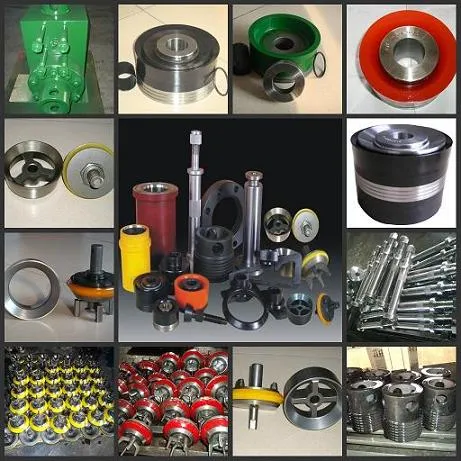
Introduction to Mud Pump Parts
Mud pump parts play a critical role in oil drilling operations by maintaining efficient drilling fluid circulation. These components ensure the continuous flow of drilling mud, which cools the drill bit, removes cuttings, and stabilizes wellbore pressure. The reliability of mud pump parts directly impacts operational safety and productivity in demanding drilling environments.
Key Components Overview
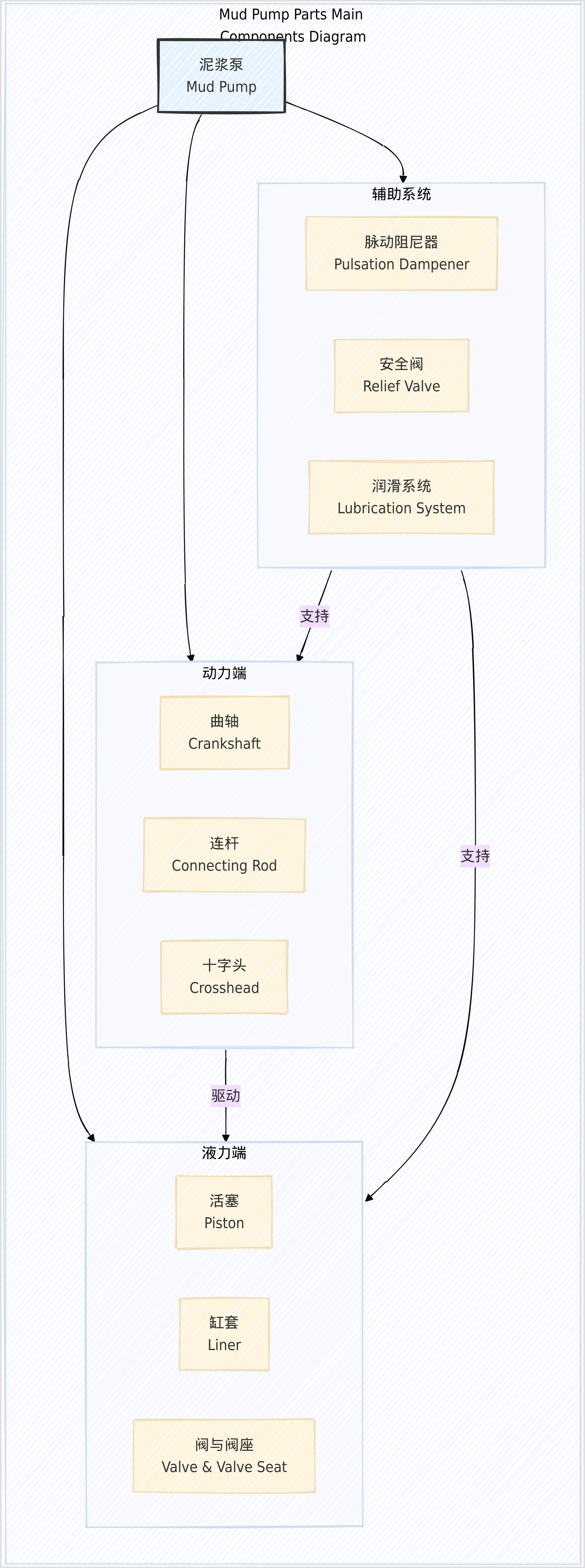
The 10 essential mud pump parts can be categorized into three functional groups, as illustrated in the diagram:
Power End Components
- Crankshaft: Converts rotational motion into reciprocating motion (Drilling Manual)
- Crosshead: Maintains alignment during motion conversion
- Gearbox: Regulates speed and torque with specific lubrication requirements
Fluid End Components
- Pistons/Plungers: Generate pressure with materials ranging from polyurethane to heat-resistant compounds (FET Product Page)
- Valves & Seats: Control fluid direction with full-open or center-guided designs for different pressures
- Liners: Chrome/ceramic sleeves withstand up to 7,500 psi working pressure (FET Fluid End Components)
Auxiliary Systems
- Pulsation Dampeners: Reduce pressure fluctuations using nitrogen-charged bladders (Drilling Formulas)
- Safety Valves: Shear-type relief valves prevent overpressure incidents (Rundong Safety Valve)
| Component | Pressure Rating | Key Material | Service Life |
|---|---|---|---|
| Ceramic Liners | 7,500 psi | Alumina ceramic | 3,000 hours |
| High-Temp Valves | 6,000 psi | Tungsten carbide | 900 hours |
| Steel Pistons | 5,000 psi | 26% Chrome Steel | 1,000 hours |
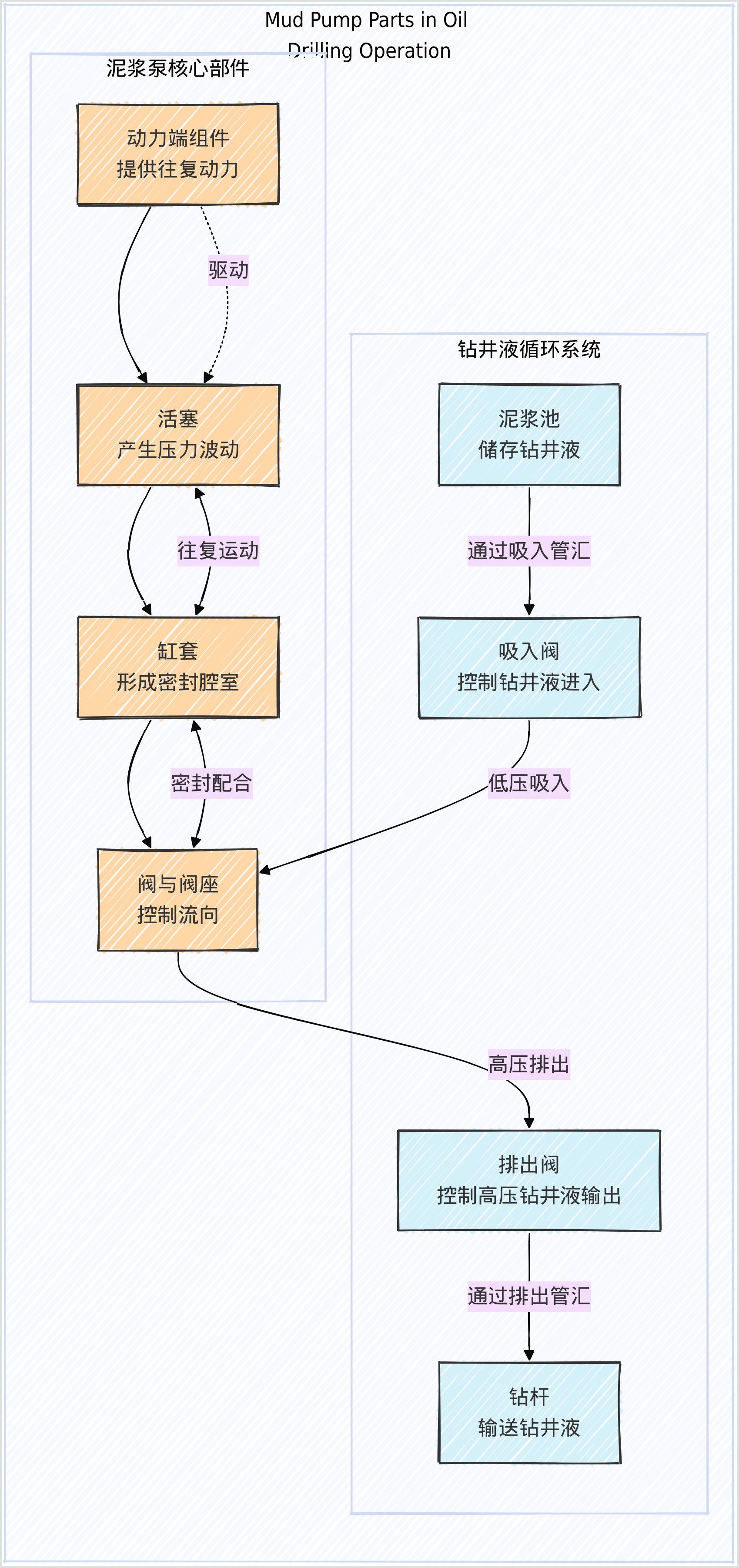
The interaction between these components is visualized in the second diagram, showing how drilling fluid moves through suction/discharge manifolds while critical parts like pistons and valves operate in synchronized cycles.
Power End Components
The power end serves as the mechanical heart of a mud pump, converting rotational energy from the prime mover into reciprocating motion to drive fluid end components. This critical assembly ensures synchronized operation under extreme drilling conditions, with its performance directly linked to pump reliability and service life.
Crankshaft and Connecting Rod
As the core load-bearing components, crankshafts and connecting rods are engineered for high cyclic stress resistance:
| Component | Material | Hardness | Fatigue Strength | Torque Capacity | Service Life* |
|---|---|---|---|---|---|
| Crankshaft | Forged 42CrMo alloy steel | 58-62 HRC | ≥850 MPa | Up to 18,000 Nm | 8,000-10,000 hrs |
| Connecting Rod | 4340 nickel-chromium steel | 32-36 HRC | ≥650 MPa | 12,000 psi W.P. | 6,000-8,000 hrs |
*Service life estimates based on API 7K standard operating conditions (Mud Pump Parts, Types & Calculations Guide – Drilling Manual). Crankshaft journals undergo precision grinding with ≤0.005mm runout, while connecting rods feature tapered bronze bushings for wrist pin articulation.
Key performance characteristics:
- Eccentricity Tolerance: ≤0.03mm across all crank throws (Gardner Denver PZ-9 Triplex Mud Pump Parts List Manual)
- Dynamic Balancing: Residual imbalance <15 g·mm/kg at 500 RPM
- Surface Finish: 0.4μm Ra on bearing surfaces
Crosshead and Gearbox
The crosshead assembly maintains linear motion alignment through dual-function design:
Crosshead Specifications:
- Guide Surface: Flame-hardened 52100 steel (60-64 HRC) with PTFE-impregnated wear strips
- Lubrication Requirements: ISO VG 320 extreme pressure oil, 30-45 psi circulation pressure
- Clearance: 0.10-0.15mm side clearance, monitored via temperature sensors (Classification and selection of mud pump spare parts – LinkedIn)
Gearbox Critical Parameters:
- Speed Reduction: Typical 4.2:1 ratio for 120-170 SPM output
- Lubrication System:
- Dual-stage filtration (25μm primary + 10μm secondary)
- Minimum flow rate: 15 L/min per 100 kW
- Oil temperature range: 40-80°C (alarm at 90°C)
- Bearing Type: Tapered roller bearings (L10 life >50,000 hrs)
Maintenance protocols emphasize:
- Oil Analysis: Monthly particle count (<ISO 18/16/13) and viscosity (±10% of nominal)
- Alignment Checks: Laser alignment ≤0.05mm/m for gear meshing
- Preload Adjustment: 0.02-0.04mm bearing preload via shim packs (Power End Assembly – American Mud Pumps)
Fluid End Components
The fluid end serves as the hydraulic core of a mud pump, directly handling high-pressure drilling fluid circulation up to 7,500 psi. This critical assembly converts reciprocating motion from the power end into pulsation-free fluid flow, with component durability directly impacting maintenance frequency and operational efficiency in abrasive drilling environments (Fluid End Pump Parts & Accessories – Forum Energy Technologies).
Pistons/Plungers and Liners
These components form a precision-matched pair that generates pressure while withstanding abrasive drilling fluids. Material selection varies based on temperature and solids content:
| Model | Pressure Rating | Temperature Range | Material Composition | Service Life* |
|---|---|---|---|---|
| Endurohead | 7,500 psi | ≤115°C | Dual-durometer polyurethane | 500-800 hrs |
| Ceramic Liner | 7,500 psi | ≤150°C | Alumina ceramic sleeve (74 HRC) | 3,000 hrs |
| Zirconia Liner | 7,500 psi | ≤180°C | ZrO₂ sleeve with 63 HRC hardness | 5,000 hrs |
| High-Temp Piston | 6,000 psi | ≤300°C | Hydrogenated nitrile rubber | 400-600 hrs |
*Service life estimates based on API 7K standard conditions (Mud Pump Parts and Expendables | Oilfield Equipment Supplies). Modern designs like FET’s Red Head piston incorporate flex-lip technology to accommodate rod misalignment while maintaining seal integrity under 240°F conditions (Classification and selection of mud pump spare parts – LinkedIn).
Valves and Seats
Valve assemblies regulate unidirectional flow with specialized designs for different operational demands:
Full-Open Valves
- Construction: Tungsten carbide inserts (≥60 HRC) with nitrile rubber seals
- Application: High-solids drilling at 5,000-7,500 psi
- Advantage: 100% flow area reduces turbulence in bentonite muds
Center-Guided Valves
- 3-Web Design: Snap-in replaceable inserts for field maintenance
- 4-Web Variant: Enhanced stability in low-solids fracturing fluids
- Pressure Limit: 6,000 psi with tapered 55° sealing surfaces
High-Temp Configurations
- Utilize fluoropolymer seals for geothermal applications
- Maintain pressure integrity up to 300°F (148°C)
- Service intervals reduced by 30% compared to standard valves
Valve/seat pairs exhibit matched wear patterns and should always be replaced as sets to maintain volumetric efficiency above 92% (Mud Pump Parts, Types & Calculations Guide – Drilling Manual).
Manifolds and Seals
The discharge/suction manifolds distribute fluid with minimal pressure loss while sealing systems prevent leaks:
Critical Parameters
- Manifold Materials: Forged ASTM A105 carbon steel with 316L stainless liners
- Connection Types:
- Studded flanges for 7,500 psi service
- Hammer unions for quick-change applications
- Seal Technologies:
- PRESS™ pony rod system reduces power end contamination by 4x
- PTFE-encapsulated O-rings for chemical resistance
Failure Prevention
- Thermal Expansion: Allow 0.15mm clearance per meter at 200°F
- Erosion Control: Ceramic wear plates at flow direction changes
- Bolt Torque: 2,500 ft-lbs for 2-7/8″ API flange studs
Proper manifold alignment using laser tools prevents eccentric loading that can crack fluid modules within 200 operating hours (Power End Assembly – American Mud Pumps).
Auxiliary Systems
Auxiliary systems form the critical support network for mud pumps, ensuring safe and efficient operation of power end and fluid end components. These systems mitigate operational risks through pulsation control, overpressure protection, and precision lubrication, with their performance directly impacting pump longevity and drilling efficiency (Mud Pump Parts, Types & Calculations Guide – Drilling Manual).
Pulsation Dampeners and Safety Valves
Pulsation Dampeners
These components stabilize fluid flow by absorbing pressure fluctuations generated during piston reciprocation. Modern dampeners utilize nitrogen-charged bladders or diaphragms to achieve:
| Parameter | Specification | Impact |
|---|---|---|
| Pressure Range | 5,000-7,500 psi | Matches standard mud pump operating pressures |
| Absorption Efficiency | Reduces pulsations by 70-85% | Minimizes vibration in discharge manifolds (Drilling Formulas) |
| Bladder Material | Nitrile/fluoropolymer composites | Resists drilling fluid corrosion up to 300°F |
| Maintenance Interval | 500-hour nitrogen pressure checks | Prevents bladder fatigue failure |
Safety Valves
Shear-type relief valves provide critical overpressure protection with these operational characteristics:
- Activation Threshold: Precisely calibrated to 110% of pump working pressure (e.g., 8,250 psi for 7,500 psi pumps)
- Response Time: <50 ms to prevent catastrophic failures
- Reset Mechanism: Requires full disassembly after activation to replace shear pins
- Installation Standards: Mandatory placement within 3 meters of pump discharge (Understanding the Shear Relief Valve in Mud Pump Systems)
Lubrication and Cooling Systems
Power End Lubrication
The gearbox and crankshaft assembly require ISO VG 320 extreme pressure oil with stringent maintenance protocols:
Filtration Standards
- Dual-stage filtration (25μm primary + 10μm secondary)
- Oil cleanliness target: ≤ISO 18/16/13 particle count
Monitoring Parameters
markdown复制| Parameter | Normal Range | Alarm Threshold | Action Required |
|--------------------|---------------|------------------|-------------------------------|
| Oil Temperature | 40-80°C | 90°C | Check cooler/circulation pump |
| Flow Rate | 15 L/min/100kW| <12 L/min/100kW | Inspect filters/piping |
| Water Content | <0.1% | >0.3% | Immediate oil change |Bearing Lubrication
- Tapered roller bearings require grease replenishment every 400 operating hours
- Automated lubrication systems reduce contamination risks by 60% (Classification and selection of mud pump spare parts – LinkedIn)
Fluid End Cooling
Closed-loop systems protect pistons and liners from thermal degradation:
- Coolant Composition: 70% water + 30% glycol mixture for freeze/boil protection
- Flow Rate: 3-5 GPM per liner to maintain surface temperature <180°F
- Nozzle Design: Fan-spray patterns ensure 360° coverage of liner interiors
- Failure Prevention: Conduct monthly inspections for nozzle clogging and hose degradation (The working principle of the drilling fluid cooling system)
Maintenance best practices emphasize:
- Quarterly replacement of coolant to prevent mineral buildup
- Installation of flow sensors to detect 15%+ flow reduction
- Use of ceramic-coated cooling manifolds in high-solids environments
Application Scenarios
The operational demands of mud pumps vary significantly across different industrial applications, with component configurations tailored to specific pressure, temperature, and wear conditions. This section examines how mud pump parts are optimized for two critical scenarios: high-pressure oil drilling and medium-pressure geological exploration.
Oil Drilling
In deep-well drilling environments, mud pump components face extreme pressures up to 7,500 psi and abrasive drilling fluids. Key adaptations include:
- High-Pressure Valves: Tungsten carbide valve/seat pairs (≥60 HRC hardness) with fluoropolymer seals withstand 6,000 psi and 300°F temperatures, reducing replacement frequency by 30% compared to conventional designs (供应API 泥浆泵阀总成).
- Ceramic Liners: Alumina ceramic sleeves (74 HRC) demonstrate a service life of 3,000 hours under 7,500 psi, outperforming steel liners in high-solids mud (泥浆泵缸套参数).
- Power End Robustness: Forged 42CrMo crankshafts with 58-62 HRC hardness maintain ≤0.03mm eccentricity under 18,000 Nm torque, critical for sustained 120 SPM operation (石油钻井用泥浆泵的工作原理及日常维护探析).
Table: Performance Comparison in Oil Drilling
| Component | Pressure Rating | Temperature Limit | Service Life |
|---|---|---|---|
| Tungsten Carbide Valves | 6,000 psi | 300°F | 900 hours |
| Ceramic Liners | 7,500 psi | 150°C | 3,000 hours |
| Forged Crankshaft | 18,000 Nm | 120°C | 10,000 hours |
Geological Exploration
Medium-pressure applications prioritize portability and maintenance efficiency:
- Lightweight Pistons: Polyurethane pistons with flex-lip designs (500-800 hr life) accommodate misalignment in BW-600/10 pumps, reducing downtime during field servicing (地质勘探的秘密武器:衡阳BW-600/10泥浆泵配件皮碗活塞深度解析).
- Modular Valves: Snap-in center-guided valve inserts enable on-site replacement without full disassembly, ideal for remote locations (如何正确进行泥浆泵的选型).
- Simplified Cooling: Air-cooled lubrication systems eliminate complex coolant circuits, suitable for exploration pumps operating below 50°C (泥浆泵在钻井中的应用).
Key Differentiators:
- Pressure Range: Exploration pumps typically operate at 1,500-3,500 psi versus 5,000-7,500 psi in oil drilling.
- Maintenance Intervals: Field-serviceable parts increase mean time between repairs by 40% in exploration scenarios (BW系列250矿用泥浆泵技术参数).
These optimizations demonstrate how material selection and system design align with operational priorities—durability for oilfield extremes versus serviceability for exploratory mobility.
Maintenance and Troubleshooting
Effective maintenance and troubleshooting of mud pump parts are critical for minimizing downtime and extending component service life in demanding drilling operations. Industry best practices suggest implementing a structured approach that combines routine inspections with predictive maintenance techniques, supported by API 7K standards (Mud Pump Liner and Piston Replacement: Best Practices Guide).
Common Failures and Causes
Frequent mud pump failures stem from abrasive wear, chemical corrosion, and operational stresses. The table below outlines key failure modes with root causes and immediate symptoms:
| Component | Failure Mode | Primary Causes | Diagnostic Symptoms |
|---|---|---|---|
| Piston/Plunger | Rubber lip degradation | – Abrasive solids in drilling fluid (≥15% concentration) | – Visible cracks/hardening (Shore A hardness drop >10%) |
| – High-temp operation (>120°C) exceeding material limits | – Fluid bypass reducing pressure by 15-20% | ||
| Valve Seat | Surface pitting | – Cavitation from pressure fluctuations (>5,000 psi cycles) | – Audible “knocking” during operation |
| – Tungsten carbide insert delamination (HRC <58) | – Flow rate inconsistency (±10% from baseline) | ||
| Liner | Eccentric wear | – Misaligned piston rod (>0.15mm runout) | – Visible scoring marks (depth >0.5mm) |
| – Inadequate cooling flow (<3 GPM per liner) | – Localized overheating (surface temp >180°F) | ||
| Mechanical Seal | Leakage | – Seal face wear exceeding API 682 limits (0.02mm/100hrs) | – Visible fluid weepage (>5 drops/minute) |
| – Vibration levels >4.5 mm/s RMS | – Contaminated lubricant (water content >0.3%) | ||
| Crankshaft Bearing | Spalling | – Oil particle contamination (ISO 18/16/13) | – Temperature spikes (>90°C) |
| – Improper preload (shim gap >0.04mm) | – Metallic debris in oil analysis |
Data compiled from (Common faults and solutions of mud pumps) and (Mud Pump Issues: problems & solutions).
Preventive Maintenance Tips
Proactive maintenance strategies can reduce unplanned downtime by up to 40% when following these API 7K-aligned practices:
Fluid End Maintenance
Liner/Piston Inspection
- Measure wear every 250 operating hours using laser profilometers
- Replace ceramic liners at 3,000 hours or when inner diameter increases by 1.5%
- Rotate liners 90° every 500 hours to distribute wear (Mud Pump Liners 101)
Valve Assembly Care
- Ultrasonic test valve seats quarterly for micro-cracks
- Always replace valves and seats as matched sets
- Apply anti-galling compound to stem threads during reassembly
Power End Protocols
Lubrication System
- Filter oil to ISO 15/13/11 cleanliness standard
- Monitor bearing temperatures with IR thermography (alert at 85°C)
- Grease crosshead guides every 400 hours using EP2 lithium-complex grease
Alignment Checks
- Verify crankshaft deflection (<0.03mm) during annual overhauls
- Laser-align gear mesh patterns every 2,000 hours
Advanced Monitoring
- Install vibration sensors on bearing housings (alert at 4.0 mm/s velocity)
- Implement oil debris sensors to detect ferrous particles >50μm (How Nabors Reduced Downtime)
Maintenance Intervals
| Task | Frequency | Reference Standard |
|---|---|---|
| Piston replacement | 500-800 hours | API 7K Annex B |
| Valve inspection | Weekly | DS-1 Tier III |
| Power end oil change | 2,000 hours | ISO 4406 |
| Safety valve testing | Every 6 months | API RP 53 |
| Full teardown inspection | 10,000 hours | Manufacturer specifications |
Adhering to these maintenance practices can extend mud pump service life by 30-50% while maintaining volumetric efficiency above 92% (7 Preventive Maintenance Best Practices).
Conclusion and Resources
The reliability and performance of mud pumps in oil drilling operations hinge on two critical factors: selecting high-quality components and adhering to rigorous maintenance schedules. As demonstrated throughout this report, each of the 10 essential mud pump parts—from power end crankshafts to fluid end ceramic liners—requires precise material specifications and operational tolerances to withstand extreme pressures up to 7,500 psi and abrasive drilling environments. Implementing API 7K-aligned maintenance protocols can reduce unplanned downtime by 40% while extending component service life by 30-50% (Mud Pump Liner and Piston Replacement: Best Practices Guide).
Where to Learn More
For further technical specifications and industry best practices, consult these authoritative resources:
| Resource Type | Key Links | Relevance |
|---|---|---|
| API Standards | API Spec 7K (2015 Edition) ISO 14693:2003 Drilling Equipment Standards | Defines material requirements and testing protocols for mud pump components |
| Manufacturer Documentation | FET Fluid End Components Gardner Denver PZ-9 Manual | Provides OEM specifications for pistons, valves, and power end assemblies |
| Technical Guides | Drilling Manual: Mud Pump Calculations IADC Safety Valve Guidelines | Covers hydraulic performance formulas and safety system configurations |
| Industry Publications | Offshore Magazine: Pump Capacity Trends SPE Paper: Condition-Based Maintenance | Analyzes emerging technologies like sensor-driven predictive maintenance |
For component selection tools and real-world failure case studies, refer to:
- Forum Energy Technologies’ Banded Bore™ liner technology demonstrating 3,000+ hour service life in high-solids mud
- American Mud Pumps’ Power End Assembly diagrams for crankshaft torque capacity benchmarks
- Oilfield Technology Magazine’s geothermal drilling reports on high-temperature valve configurations
These resources collectively provide the technical depth needed to optimize mud pump performance while meeting API 7K and ISO 14693 compliance requirements (PDFAPI Standards: International Usage Report).