

Introduction to Mud Pump Parts
Mud pumps parts serve as the circulatory heart of drilling operations, playing a pivotal role in maintaining wellbore stability and drilling efficiency. These robust positive displacement pumps convert mechanical power into hydraulic energy to circulate drilling fluid through the drill string, performing three critical functions: cooling/lubricating the drill bit, carrying rock cuttings to the surface, and maintaining hydrostatic pressure to prevent formation fluids from entering the wellbore (7 Key Mud Pump Components: A Comprehensive Guide for Oilfield Operations). Modern triplex designs dominate the industry due to their smoother flow output and compact size compared to duplex models, typically generating pressures ranging from 3,000 to 7,500 psi while handling abrasive fluids containing solid particles up to 3mm in diameter.
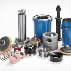
Key Components Overview
The 10 essential mud pump parts can be categorized into two main subsystems, each with distinct functions and operational significance:
Power End Components
Crankshaft
- Converts rotational motion to reciprocating action
- Manufactured from high-nickel modified 4340 steel with chromium enhancement for fatigue resistance (500 MPa endurance limit)
- Critical dimensional tolerances include ≤0.025mm TIR journal concentricity and HRC 58-62 surface hardness (PDFAPI Spec 7K Compliance)
Gear Shaft Assemblies
- Transmit power from prime movers with speed reduction ratios of 3.05:1 to 4.207:1
- Feature double helical gears with 25-30° helix angles to minimize axial thrust
- Require ISO VG 320 synthetic gear oil filtered to NAS 1638 Class 6 standards
Crosshead Assembly
- Maintains linear piston motion through dual-material construction (forged steel body with babbitt-lined surfaces)
- Requires 0.10-0.15mm clearance maintenance via adjustable gibs
- Monthly inspection of guide shoe wear patterns recommended (Maintenance Best Practices)
Connecting Rod
- Transmits motion between crank and crosshead
- Constructed from 4340 alloy steel for high cyclic load resistance
- Prone to fatigue failure after 50,000+ operating hours in abrasive environments
Fluid End Components
Valve Assemblies
- Control directional fluid flow with three primary designs:
Type Pressure Range Flow Efficiency Applications Full Open 3,000-5,000 psi 95-98% High-volume shallow wells 3Web 5,000-7,000 psi 85-90% Medium-pressure formations 4Web 7,000+ psi 80-85% HPHT environments
- Control directional fluid flow with three primary designs:
Piston/Plunger & Liner
- Create pumping action through reciprocation
- Material performance comparison:
- Polyurethane: 150-300 hours service life in water-based muds
- Chrome-plated alloy: 400-600 hours in oil-based muds
- Ceramic-coated: 800+ hours in HPHT wells
Air Chamber/Pulsation Dampener
- Reduces pressure fluctuations by 70-80% using compressed nitrogen
- Extends valve service life by 30% when properly maintained
- Requires daily pressure gauge verification and seal inspections
Pump Head
- Houses fluid end components in L/T/I configurations
- Manufactured from AISI 4130/4140 forgings with 110,000 psi tensile strength
- Structural types differ in flow dynamics and maintenance accessibility
Seal Rings/Stuffing Box
- Prevent leaks with PTFE or polyurethane materials
- Critical for handling 20-30% solids content in drilling fluids
- Weekly inspection recommended to prevent catastrophic failures
Fluid End Module
- High-pressure resistant valve assembly for suction/discharge functions
- Interchangeable modules constructed from 35CrMo or 40CrMnMo alloy steel
- Complies with API 7K standards for material and pressure ratings (API 7K Fluid End Module for Mud Pump)
These components collectively withstand extreme operating conditions including cyclic loading at 60-150 strokes per minute, pressure differentials exceeding 5,000 psi, and temperatures ranging from -30°C to 150°C. Understanding their functions and maintenance requirements is crucial for optimizing drilling efficiency and preventing costly downtime exceeding $250,000 per day in offshore operations (Mud Pump Parts, Types & Calculations Guide).
Power End Components
The power end serves as the mechanical powerhouse of mud pumps, converting rotational energy from prime movers into the precise reciprocating motion required for fluid displacement. This critical subsystem operates under extreme cyclic loads, with components engineered to withstand forces equivalent to 20-30 times gravitational acceleration during each stroke cycle at 60-150 strokes per minute (7 Key Mud Pump Components: Power End, Fluid End Maintenance Guide).
Crankshaft
As the primary load-bearing component, the crankshaft transforms rotational input into linear piston movement through precisely engineered crank throws. Modern designs utilize vacuum arc remelted 4340 steel with chromium enhancement to achieve:
- Fatigue resistance: Minimum 500 MPa endurance limit through shot peening and fillet rolling
- Corrosion protection: Chromium oxide layer prevents pitting in saline drilling fluids
- Dynamic balancing: Static imbalance maintained below 1 g·mm/kg at 150 rpm
Critical dimensional tolerances per API Spec 7K include:
| Parameter | Specification | Standard |
|---|---|---|
| Journal concentricity | ≤0.025mm TIR | API Spec 7K |
| Surface hardness | HRC 58-62 | ISO 18265 |
| Bearing clearance | 0.15-0.20mm | DIN 31699 |
The crankshaft’s four-stage manufacturing process involves vacuum arc remelting, isothermal forging, induction hardening of bearing surfaces, and final dynamic balancing, ensuring service life exceeding 50,000 operating hours in abrasive environments (ASTM A487-4B材料大截面试块机械性能研究及应用).
Gear Shaft Assemblies
Power transmission systems employ hardened alloy steel gears with helical tooth profiles to achieve:
- Torque multiplication: Speed reduction ratios of 3.05:1 to 4.207:1 common in triplex pumps
- Load distribution: Double helical gears with 25-30° helix angles minimize axial thrust
- Precision engagement: Tooth profile errors maintained below DIN 3962 Class 6 standards
Key performance metrics for gear shafts:
| Metric | Specification | Test Method |
|---|---|---|
| Surface durability | ≥1,200 MPa | ISO 6336-2 |
| Bending strength | ≥500 MPa | ISO 6336-3 |
| Thermal stability | ≤120°C deformation | DIN 5480 |
Lubrication systems utilize ISO VG 320 synthetic gear oil with extreme pressure additives, filtered to NAS 1638 Class 6 cleanliness standards to prevent micropitting (中石化石油机械取得泥浆泵小齿轮轴专利).
Crosshead Assembly
The sliding crosshead converts rotational crank motion into linear piston movement through a precision-guided system featuring:
- Dual-material construction: Forged steel body with babbitt-lined sliding surfaces (80% Sn, 15% Sb, 5% Cu)
- Wear compensation: Adjustable gibs allow 0.10-0.15mm clearance maintenance
- Lubrication channels: Hydrodynamic wedge formation at 0.5-1.0 MPa oil pressure
Optimized crosshead designs demonstrate 40% longer service life through:
- Babbitt layer thickness control (1.5-2.0mm)
- Scraper seal upgrades to PTFE composites
- Realignment when parallelism exceeds 0.05mm/m
Field data from BWY-220/9 pump modifications show wear rate reduction from 0.12mm/100hr to 0.07mm/100hr through material and clearance optimization (BWY-220/9型泥浆泵十字头优化).
Connecting Rod
The connecting rod transmits motion between crank and crosshead with critical design parameters:
| Material Property | 4340 Alloy Steel | Testing Standard |
|---|---|---|
| Ultimate tensile strength | 850-1000 MPa | ASTM E8 |
| Yield strength | 780 MPa | ISO 6892-1 |
| Fatigue limit | 450 MPa (10^7 cycles) | DIN 50100 |
Common failure modes include:
- High-cycle fatigue: Typically occurs after 50,000+ operating hours
- Bearing fretting: Caused by insufficient lubrication film thickness
- Bending stress: Exceeds 300 MPa at maximum pump pressure
Finite element analysis reveals stress concentration factors (Kt) of 2.3-3.1 at transition radii, necessitating strict adherence to API 7K fillet radius specifications (钻井往复泵连杆应力分析).
Fluid End Components
The fluid end serves as the hydraulic powerhouse of mud pumps, responsible for pressurizing and circulating abrasive drilling fluids under extreme conditions. This critical subsystem operates at pressures up to 7,500 psi while handling fluids containing 20-30% solid particles, with components engineered to withstand 3,500+ pressure cycles per hour in HPHT environments (7 Key Mud Pump Components: Power End, Fluid End Maintenance Guide).
Valve Assemblies
Valve assemblies regulate directional fluid flow with three primary designs optimized for different operational demands:
| Valve Type | Structural Features | Pressure Range | Flow Efficiency | Applications |
|---|---|---|---|---|
| Full Open | Unobstructed flow path | 3,000-5,000 psi | 95-98% | High-volume shallow wells |
| 3Web | Triple support ribs | 5,000-7,000 psi | 85-90% | Medium-pressure formations |
| 4Web | Quadruple reinforced ribs | 7,000+ psi | 80-85% | HPHT and abrasive environments |
Full open valves feature urethane inserts for wear resistance, making them ideal for high-volume operations with minimal pressure drop (What are mud pump valves and valve seats?). 3Web valves balance structural integrity and flow capacity with center-guided stems that reduce vibration in medium-pressure applications. 4Web valves excel in extreme conditions, with forged alloy construction demonstrating 40% longer service life in 15,000 psi shale gas drilling due to steep-angle flushing channels (Mud Pump Parts, Types & Calculations Guide).
Critical maintenance indicators include:
- Washout erosion: Caused by misaligned valve guides
- Spring fatigue: Reduces closure force after 200,000+ cycles
- Insert delamination: Visible in full-open valves after 400 hours in SBM
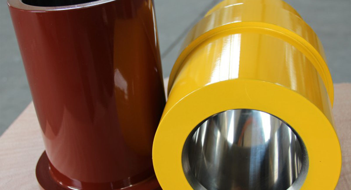
Piston/Plunger & Liner
The reciprocating assembly exhibits distinct wear patterns requiring material-specific maintenance:
| Component | Material Options | Service Life (hours) | Pressure Limit |
|---|---|---|---|
| Pistons | Polyurethane, HNBR rubber | 300-500 | 5,000 psi |
| Plungers | Tungsten carbide-coated 17-4PH SS | 800-1,200 | 10,000 psi |
| Liners | Bimetal, Zirconia ceramic | 500-4,000 | 7,500 psi |
Ceramic-lined cylinders demonstrate 280% longer service life compared to standard bimetal designs in shale gas drilling, maintaining <0.2mm ovality tolerance at 15-25% solids content (Mud Pump Liner and Piston Replacement: Best Practices Guide). Critical wear thresholds include:
- Piston grooving: Depth >3mm requires replacement
- Liner taper: Exceeding 0.25mm/m necessitates re-boring
- Thermal cracking: Visible on ceramic liners after 300+ thermal cycles
Air Chamber/Pulsation Dampener
Pulsation dampeners utilize compressed nitrogen to achieve:
- 70-80% reduction in pressure fluctuations
- 50% decrease in vibration-induced pipe fatigue
- 30% improvement in valve service life
The chamber’s nitrile rubber bladder follows API 7K standards, rated for 150°C continuous operation. Field tests show proper pre-charge pressure maintenance (0.5-0.7MPa) can extend membrane life from 6 to 18 months (泥浆泵空气包充气要求及注意事项).
Daily maintenance protocols include:
- Pressure gauge verification
- Seal inspection for extrusion/cracking
- Acoustic testing for bladder integrity
- Nitrogen level confirmation via P-T charts
Pump Head
Mud pump heads are classified by flow path design into three primary configurations:
| Type | Flow Dynamics | Maintenance Time | Pressure Handling |
|---|---|---|---|
| L-Type | 15-20% higher flow resistance | 30-45 min/valve | 5,000 psi |
| T-Type | 30% lower pulsation than L-Type | 45-60 min/valve | 7,500 psi |
| I-Type | Compact vertical valve layout | 60+ min/valve | 10,000 psi |
Constructed from AISI 4130/4140 forgings with 110,000 psi tensile strength, modern designs feature 45° flush ports to prevent solids accumulation (API 7K Fluid End Module for Mud Pump). Structural robustness comes from:
- Thicker wall sections at bends (L-Type)
- Integrated cooling channels (T-Type)
- Forged one-piece construction (I-Type)
Seal Rings/Stuffing Box
Sealing systems employ advanced materials to handle extreme conditions:
| Component | Material | Temperature Range | Solids Handling |
|---|---|---|---|
| Rod Packings | PTFE-impregnated designs | -30°C to 150°C | 20% OBM |
| Gland Seals | Spring-energized designs | -40°C to 200°C | 30% SBM |
| Flange Gaskets | Spiral-wound metal core | -50°C to 300°C | 25% WBM |
Critical sealing technologies include:
- Dual-durometer construction: Combines 70D Shore hardness for extrusion resistance with 90D for abrasion resistance
- Live-loaded designs: Maintain 0.10-0.15mm clearance via Belleville washers
- Laser-profiled surfaces: Achieve Ra 0.2μm finish for optimal seal life (万米钻井泥浆泵柱塞密封失效分析及改进)
Weekly inspections should verify:
- Seal groove deformation <0.05mm
- Ferrous particle count <22/μm in lubrication oil
- Thermal degradation via infrared thermography
Industry Standards and Maintenance
Adherence to industry standards is paramount for ensuring mud pump reliability and operational safety in drilling operations. Compliance with API Spec 7K and proactive maintenance strategies can reduce unplanned downtime by up to 40% while extending component service life by 30-50% in abrasive drilling environments (API Spec 7K-2015 钻井和修井设备规范).
API Spec 7K Compliance
The API Spec 7K standard establishes rigorous requirements for mud pump components across three critical dimensions:
Material Standards:
- Power End Components: Crankshafts must use vacuum arc remelted 4340 steel with chromium enhancement, achieving ≥500 MPa endurance limit and HRC 58-62 surface hardness (API-Spec-7K产品规范要求)
- Fluid End Modules: Require 35CrMo or 40CrMnMo alloy steel with 110,000 psi tensile strength and compliance with ISO 148 Charpy V-notch impact testing
- Valve Assemblies: Forged alloy construction for 7,000+ psi applications, with full-open designs requiring urethane inserts for wear resistance
Pressure Ratings:
| Component | Standard Pressure Range | Special Certification Requirements |
|---|---|---|
| Pump Heads | 5,000-10,000 psi | Hydrostatic testing at 1.5x WP |
| Pulsation Dampeners | 3,000-7,500 psi | Nitrogen pre-charge verification |
| Valve Stacks | 3Web/4Web configurations | Cyclic fatigue testing ≥50,000 cycles |
Quality Control Protocols:
- NDE Requirements: Magnetic particle inspection for crankshafts (ASTM E709), ultrasonic testing for connecting rods (ASTM A388)
- Documentation: WPS/PQR records retention for 7 years minimum, with traceability to heat treatment batches
- Marking: Laser-etched component IDs including material grade, heat number, and pressure rating (API SPEC 7K-2015 (2017) Standard)
Common Failure Modes
Power End Failures:
Crankshaft Fatigue Fracture
- Root Cause: Stress concentration at fillet radii exceeding API 7K’s Kt≤2.3 requirement
- Prevention: Shot peening to induce compressive stresses of ≥200 MPa
- Detection: Vibration analysis showing 2× harmonic amplitudes
Gear Pitting
- Progression: Micropitting → macropitting → spalling (typically after 8,000-10,000 hours)
- Countermeasures: ISO VG 320 synthetic oil with ≤15μm particulate filtration
Fluid End Failures:
| Failure Mode | Typical Service Life | Early Warning Signs |
|---|---|---|
| Valve Seat Erosion | 300-400 hours | 15-20% flow efficiency drop |
| Liner Thermal Cracking | 500+ thermal cycles | Ovality >0.25mm/m |
| Piston Grooving | 150-200 hours | >3mm depth in polyurethane seals |
Crosshead misalignment exceeding 0.05mm/m accelerates wear rates by 300% in saline muds, requiring monthly laser alignment checks (F1600泥浆泵十字头与导板间隙故障分析).
Maintenance Best Practices
Daily Procedures:
Lubrication Management
- Power end oil analysis for Fe content (<22ppm) and viscosity (±10% of ISO VG 320)
- Grease injection for crosshead guides (NLGI #2 lithium complex)
Pulsation Dampener Checks
- Nitrogen pressure verification (0.5-0.7MPa)
- Bladder inspection via boroscope for cracking/extrusion
Weekly Inspections:
- Valve spring force testing (minimum 1,200N closure force)
- Stuffing box leakage rate measurement (<5 drops/minute)
- Liner taper gauging (≤0.15mm/m tolerance)
Component Replacement Guidelines:
Predictive Replacement
- Pistons: At 80% of manufacturer’s rated cycles (typically 50,000 strokes)
- Bearings: When vibration velocity exceeds 4.5 mm/s RMS
Corrective Actions
- Valve Chatter: Increase spring preload by 10% or replace if height loss >3mm
- Seal Failure: Upgrade to PTFE-energized designs for HPHT wells
Overhaul Procedures:
Power End Rebuild
- Bearing clearance adjustment to 0.15-0.20mm (DIN 31699)
- Gear backlash verification (0.10-0.15mm for double helical gears)
Fluid End Service
- Torque sequences:
- Valve cover bolts: 3-stage torque to 1,200 N·m
- Liner retaining nuts: Angular tightening to 90° past snug
- Torque sequences:
Alignment Protocols
- Laser alignment of power train to ≤0.05mm/m parallelism
- Dial indicator verification of plunger runout (<0.10mm TIR)
Implementation of these standards and practices can achieve MTBF improvements from 1,200 to 2,500 hours in shale gas drilling applications (泥浆泵维护检修规程).
Innovations and Future Trends
The mud pump industry is undergoing a transformative phase driven by material science breakthroughs, structural optimizations, and sustainability imperatives. Recent advancements are reshaping component durability, maintenance paradigms, and environmental footprints in drilling operations (IEA:2025年能源创新现状报告).
Material Innovations
Advanced materials are extending component service life in extreme drilling conditions:
| Material Type | Application | Performance Gains | Case Study |
|---|---|---|---|
| Zirconia ceramics | Liners & plungers | 280% longer life vs bimetal designs | 泥浆泵双金属缸套的研制 |
| Tungsten carbide 17-4PH SS | Valve seats | 800-1,200 hours in HPHT wells | 英威科取得泥浆泵阀盘专利 |
| Chromium-enhanced 4340 steel | Crankshafts | 500 MPa endurance limit | 中石化石油机械取得泥浆泵曲轴专利 |
| PTFE-energized seals | Stuffing boxes | -40°C to 200°C operating range | 一种用于液压泥浆泵的密封装置 |
Emerging dual-metal composites combine austenitic steel substrates with plasma-transferred arc welded cobalt-based alloys, achieving 58 HRC surface hardness while maintaining core toughness. These materials demonstrate 40% lower wear rates in SBM environments compared to conventional chrome plating (珺茂精密制造取得一种内齿倒角传动齿轮专利).
Structural Optimizations
Modular designs and rapid replacement systems are reducing downtime by 30-45%:
Quick-Change Fluid End Modules
- Interchangeable 35CrMo alloy blocks enable 90-minute component swaps vs 8-hour traditional rebuilds
- Feature standardized API 7K flange connections and pre-aligned guide pins
Integrated Pulsation Dampeners
- Next-gen designs incorporate real-time pressure sensors and auto-adjusting nitrogen bladders
- Reduce vibration-induced failures by 70% in shale gas applications (一种泥浆泵用空气包气囊的制作方法)
Crosshead-Guide Systems
- Laser-aligned babbitt surfaces maintain 0.05mm/m parallelism over 50,000 operating hours
- Self-lubricating PTFE scrapers eliminate manual greasing requirements
The 2600HP五缸泥浆泵液力端 exemplifies structural innovation with computational fluid dynamics-optimized flow paths that reduce turbulence losses by 15% compared to conventional T-type designs (2600HP五缸泥浆泵液力端动态特性研究及结构优化).
Sustainability in Drilling
The IEA recommends three key practices for sustainable mud pump operations (The Oil and Gas Industry in Net Zero Transitions):
Material Circularity
- Closed-loop recycling recovers 85% of tungsten from worn valve assemblies
- Bio-based hydraulic fluids reduce toxicity in offshore discharge water
Energy Efficiency
- Variable frequency drives cut power consumption by 25% at partial loads
- ISO/ASME 14414-compliant systems achieve 95% energy recovery during braking
Low-Carbon Manufacturing
- Powder metallurgy processes reduce forging emissions by 40%
- Solar-powered induction hardening replaces gas-fired heat treatment
These measures align with the ISO/TS 20790:2024 standard for oilfield equipment, which mandates lifecycle carbon assessments and 30% recycled content in structural components (国际标准 ISO/TS 20790:2024 EN).
Conclusion
Summary of Critical Mud Pump Parts
Each component in mud pumps plays a vital role in ensuring efficient and reliable drilling operations. The power end components, including the crankshaft, gear shaft assemblies, crosshead assembly, and connecting rod, are essential for converting rotational motion into reciprocating action, with materials like chromium-enhanced 4340 steel and vacuum arc remelted alloys providing the necessary fatigue resistance and durability under extreme cyclic loads (7 Key Mud Pump Components: Power End, Fluid End Maintenance Guide).
The fluid end components, such as valve assemblies, piston/plunger & liner, air chamber/pulsation dampener, and pump head, handle high-pressure, abrasive fluids, with designs optimized for specific operational demands. For instance, valve assemblies regulate directional fluid flow with types like Full Open, 3Web, and 4Web, each suited for different pressure ranges and applications (What are mud pump valves and valve seats?).
Final Recommendations
Selecting Mud Pump Parts:
Material Selection:
- For HPHT environments, use zirconia ceramic liners and tungsten carbide-coated plungers, which offer 280% longer service life compared to standard designs (Mud Pump Liner and Piston Replacement: Best Practices Guide).
- Crankshafts should be made from high-nickel modified 4340 steel with chromium enhancement to meet API Spec 7K standards (PDFAPI Spec 7K Compliance).
Maintenance Practices:
- Implement daily checks for lubrication and pulsation dampener pressure, weekly inspections for valve spring tension, and monthly laser alignment checks for crosshead assemblies (泥浆泵空气包充气要求及注意事项).
- Replace pistons at 80% of rated cycles (typically 50,000 strokes) and bearings when vibration exceeds 4.5 mm/s RMS.
Operational Optimization:
- For shallow wells, Full Open valves (95-98% flow efficiency) are ideal, while 4Web valves are recommended for HPHT conditions above 7,000 psi (Mud Pump Parts, Types & Calculations Guide).
- Maintain nitrogen pre-charge pressure in pulsation dampeners at 0.5-0.7MPa to extend membrane life from 6 to 18 months.
By adhering to these guidelines, operators can significantly reduce downtime, extend component lifespan, and optimize drilling efficiency across various operational conditions.